With the Dcc Monitor you can “see” the DCC packets transmitted in your layout tracks ! Your just need an Arduino Uno and some skills in electronics.
Quick overview
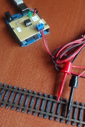
- The Arduino collect continuously Dcc packets from tracks (it reads 0 and 1 bits)
- Every second the Arduino send packets to the computer through the serial port (emulated on USB)
- Dcc Monitor application on computer translate raw packets and display information on the screen.
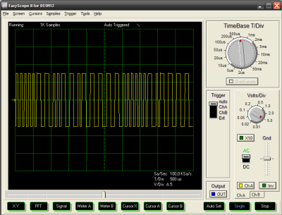
Dcc packets seen on an oscilloscope
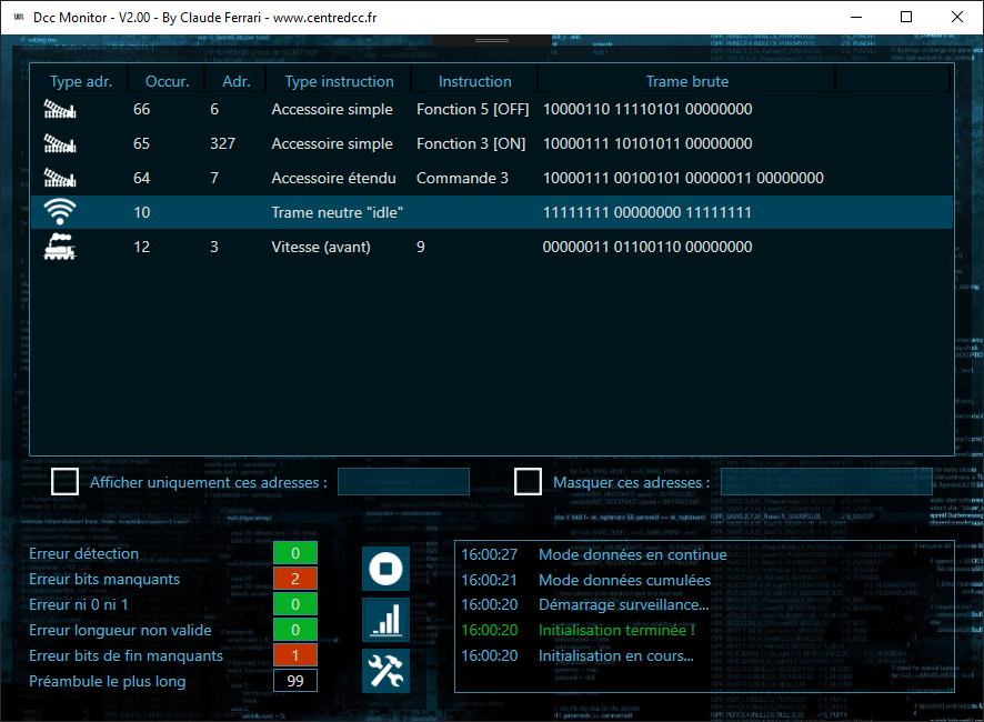
Translated packets in the application
Necessary materials
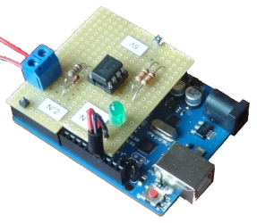
Electronic board
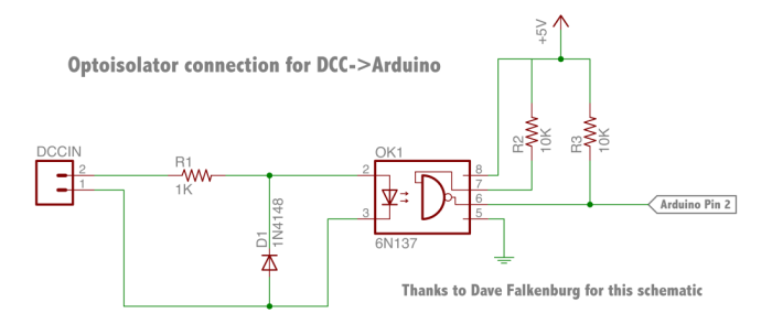
Components used and diagram
- 10K resistors (x2)
- 1K resistor
- Diode 1N4148
- Optoisolator 6N137
- LED 5V
- Screw terminal
- Pin headers
- Oscilloscope probes
Source : http://www.mynabay.com/
Download
- Arduino library used : (v 1.03) : DCC_Decoder
- Arduino code (v 1.05) : My_DCC_Monitor
- Computer application (v 2.02) : Dcc Monitor
Setup
- Install Arduino IDE (development environment)
- Install the DCC_Decoder library
- Compile and upload program into the Arduino
- Copy the DccMonitor.exe and the library in the Dcc Center application main folder
- Default folder : C:\Program Files (x86)\Ferrari Software\DccCenter
- Launch DccMonitor.exe application